555 guide
Falstad
What is Falstad
Falstad is a free browser tool where you can build and simulate electronic circuits and inspect them. You simply drag parts onto canvas, wire them up and then run the simulation. Falstad lets us see what's happening inside our circuits, like how voltage and current change over time.
Getting Started with Falstad
To get started, first head on over to https://www.falstad.com/circuit/circuitjs.html
By default, there's a circuit on the canvas. Get rid of it by either selecting and deleting the parts, or go to File → New Blank Circuit for a clean slate.
Now the black space is your canvas, drag to pan, scroll to zoom, click to place stuff.
Top bar: Commonly used components (voltage sources, resistors, LEDs).
Right sidebar: Run/pause simulation, speed control, reset button.
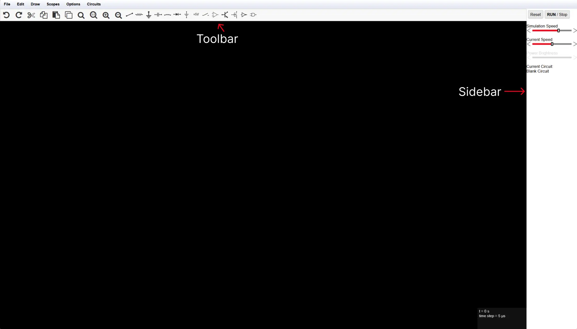
Adding Components
You can add components by either selecting them from the top bar or by using the special drop down menu that opens when you right click anywhere on the canvas. Once you select the component you need to press anywhere on the canvas and drag the mouse to place it.
If you want to edit the value of a component, you can do so by right clicking it and selecting edit. If you want to try out multiple values you could also add a slider, which lets you change the component's value by using a slider.
Viewing Output
If you wanted to know how much current was flowing through one point and what its voltage relative to ground was you can easily know that by viewing in a scope!
You can open a scope at any point of your circuit by simply right clicking on that point and selecting View in New Scope/View in New Undocked Scope.
This is really helpful for debugging circuits and understanding how they work, since sometimes your circuit looks fine from the outside (LEDs blinking, whatever) but the scope shows the actual voltage/current doing something totally different from what you expected.
Building Your First 555 Circuit
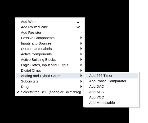
Let's start by placing a 555 on the canvas, the 555 timer can be found under Analog and Hybrid Chips
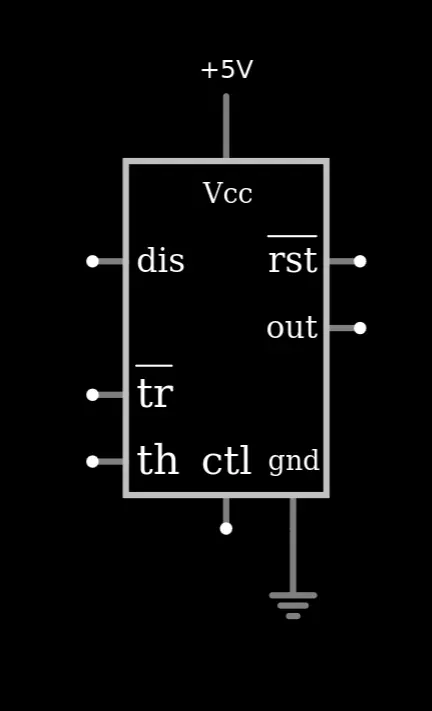
I'll start off by wiring its supply voltage and ground with a voltage source and ground flag.
Then I'm going to wire it up so it's in astable mode with an LED connected to the output temporarily just to see the output alongside the scope.
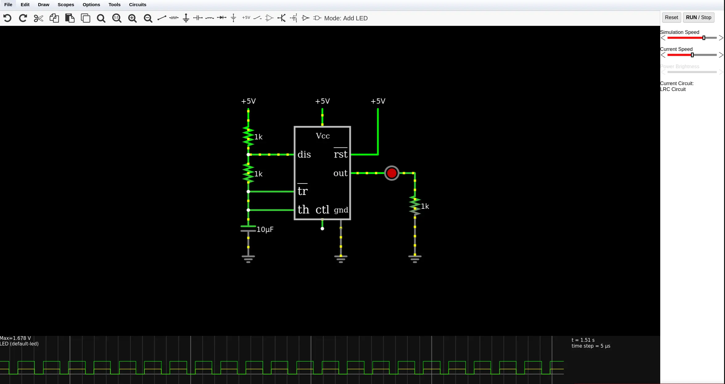
Once confirmed that it's working I'll place a Ring Counter (which can be found under Digital Chips)
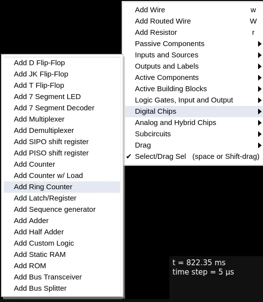
I'll rotate it and wire its CLK pin to the output of the 555, I'll also right click and edit the counter and invert its reset pin.
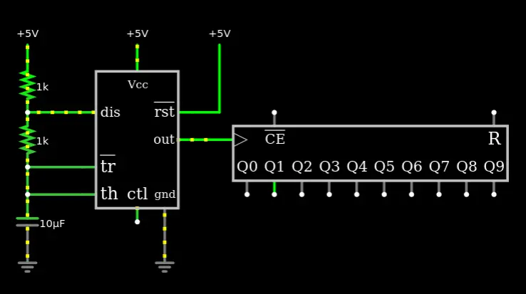
If you run the simulation right now you'll see the outputs Q0-Q9 sequentially counting up. To finish up my circuit I'll add LEDs to the ring counter's output with a current limiting resistor at the end.
And there you have it! Now you understand how blinky boards work, if you've ever built one.
Saving and Sharing Your Circuit
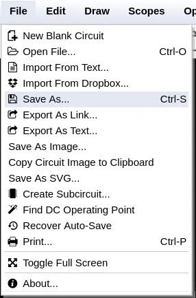
To save your circuit you can just simply go File → Save As and for getting a link you can just select Export As Link...
For example, here's the URL for the circuit I showed above https://www.falstad.com/s.php?s=poUOqs